Shape the panels
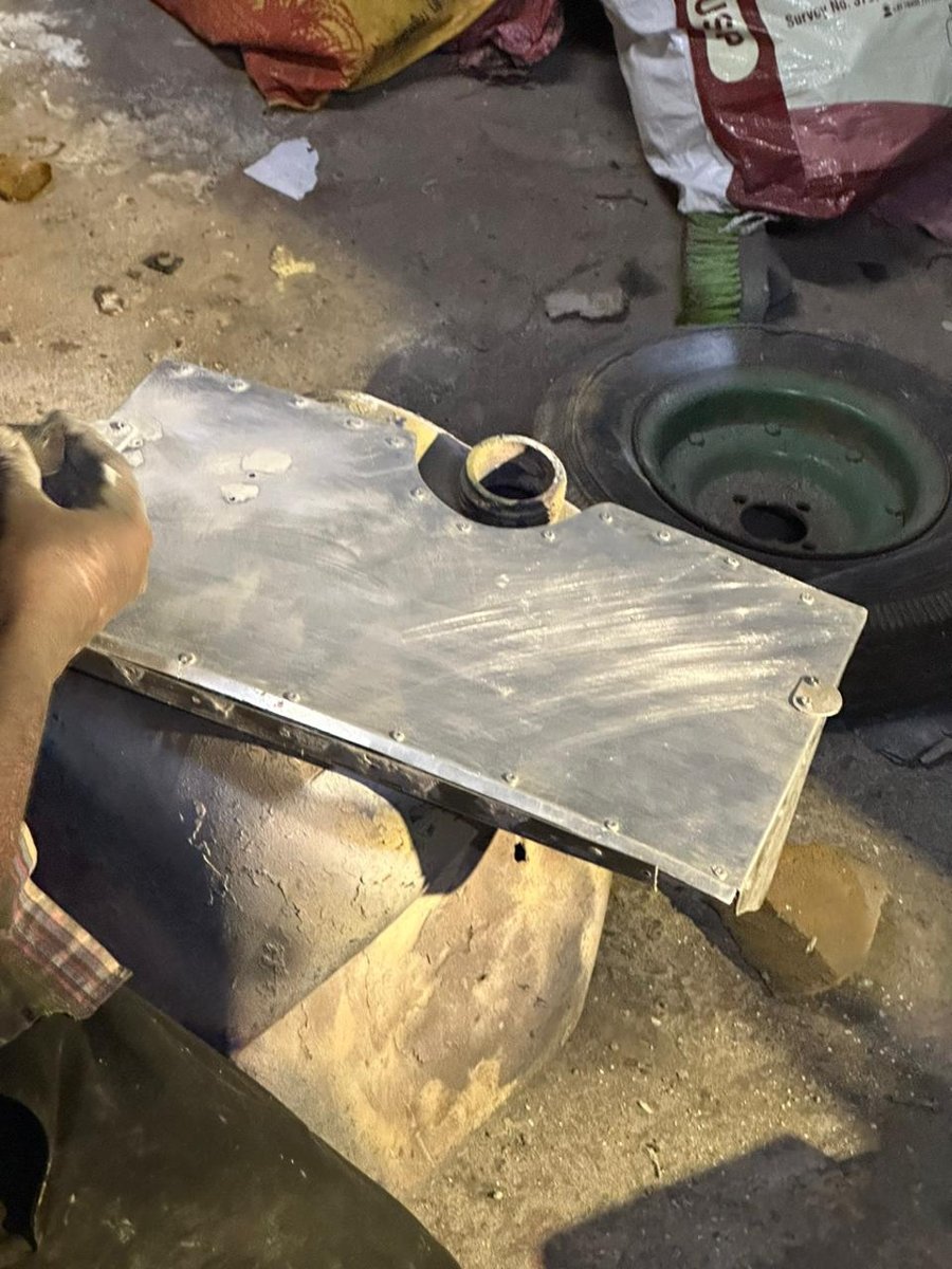
The team compared forming approaches and selected hammer forming for the embossed upper panel, considering practicality and cost. Other sheet parts were cut and bent to shape.
AIRCRAFT MANUFACTURING / FIRST-YEAR TEAM PROJECT
A Piper Seneca 2 manufacturing prototype that connected material selection, forming, assembly and finishing.
My first-year team project provided practical exposure to the work behind a physical aircraft component. The report records the build sequence and the specialist workshop support used along the way.
See the manufacturing sequence ↓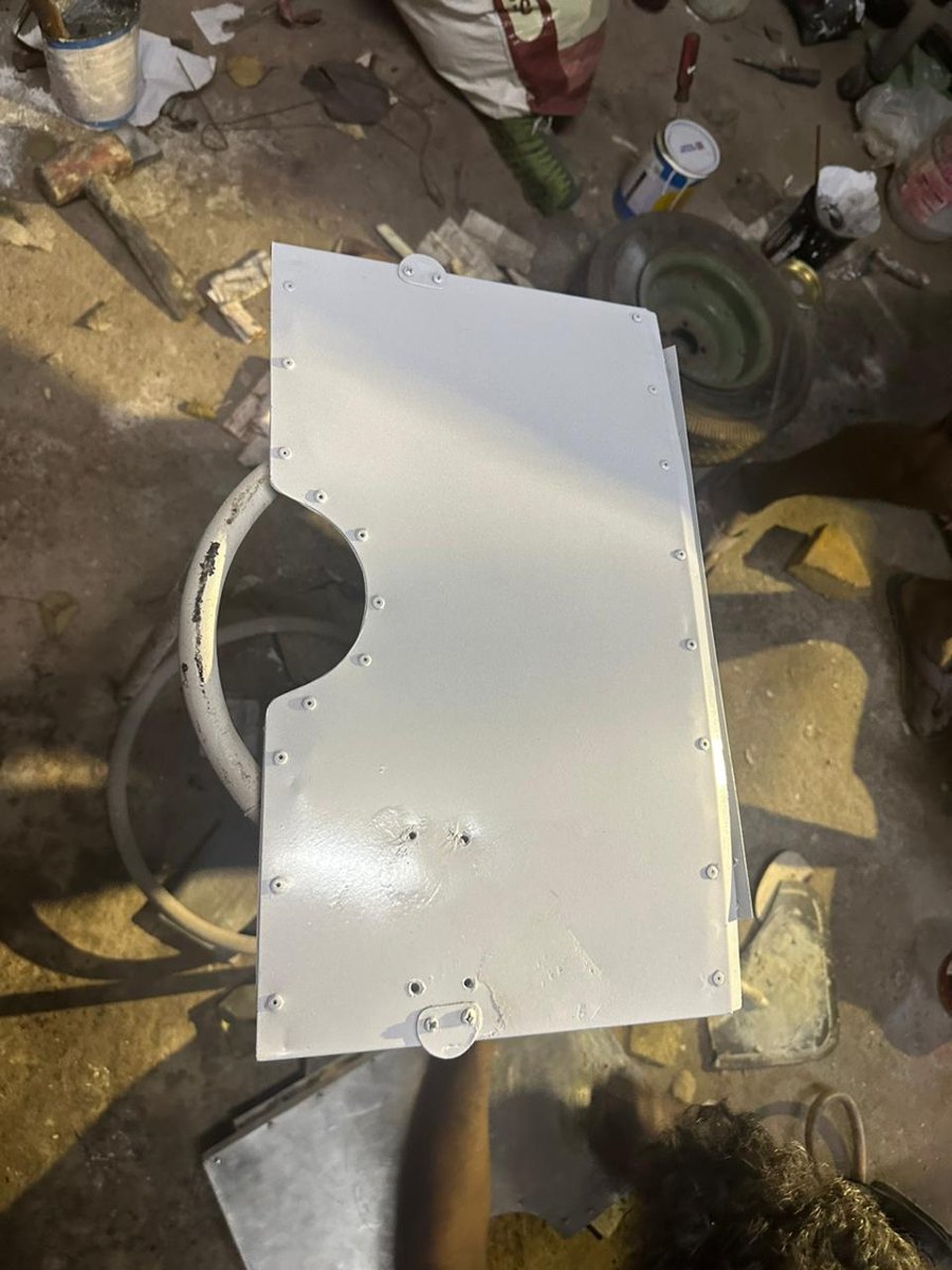
01 / MANUFACTURING SEQUENCE
The team compared forming approaches and selected hammer forming for the embossed upper panel, considering practicality and cost. Other sheet parts were cut and bent to shape.
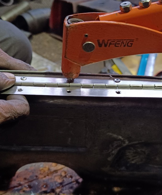
Hinges, connecting rods and linkage parts were prepared through drilling and lathe operations. Rivets joined the panel halves and hinge connector. The report also records specialist-supported GTAW work on linkage parts.
Grinding and filler addressed surface condition before the reported heat-resistant finish was applied. The build photographs retain the sequence from unpainted assembly to finished prototype.
02 / PRACTICAL LEARNING
My contribution was as a member of the student project team. The evidence supports experience with the manufacturing sequence, coordination around workshop access and the relationship between formed parts, joints and assembly.
The project record includes the manufacturing report, original build photographs and five SolidWorks part files.
03 / SCOPE AND NEXT STEP
This project demonstrates academic manufacturing and assembly experience. It does not establish flight installation, airworthiness approval, cooling performance or a production-qualified part.
A separate “future modifications” document proposes sensors, an ECU, actuation, feedback and manual override. This remains a concept: completed control hardware, flight integration and measured efficiency improvements are not evidenced.
Source: supplied team manufacturing reports and original build photographs. Academic work; no manufacturer affiliation or endorsement is implied.